

Back in December the Index Typewriter – AEG Mignon popped up on Thingiverse. Having just bought a 3d printer, and being subscribed to some typewriter forums, this was very much aligned with my interests and I heard about it rather quickly. But surely, this is much too ambitious of a build for a newcomer to 3d printing! But MJ was up to the challenge, and we began tackling it on February 7th.
To back up a moment: What’s an Index Typewriter? Instead of using a keyboard with an arm for each key (or combination of keys), an index typewriter instead uses a flat reference “index” that you use a stylus with to point to the letter you want. The stylus is connected to the Type Element that rolls to your letter, number, or symbol when you hit a lever to strike. Ultimately, it’s a much simpler design than traditional typewriters, which made it an excellent choice for the world’s first 3d printed typewriter!
Also, if this sounds vaguely familiar, Madame Morrible uses a Mignon index typewriter in Wicked: For Good. It’s right after the scene where The Wizard is sitting in front of an Oliver typewriter. I was delighted!
Anyway, I printed the Index_Typewriter_Hardware_and_Printing_Guide.pdf and Index_Typewriter_Assembly_Guide.pdf so I could peruse offline, and ultimately use it for assembly. The first thing I’ll say about these is that the author, Keenan Finucan, did a spectacular job. They’re detailed and every step has pictures to help figure out the correct placement of things, and photographs where needed. I only needed to ask for a handful of clarifications throughout this process so far.
I bought this spring set on Amazon, which had almost all the spring sizes I needed (and the missing smaller one I was able to cut down from a larger) and picked up a standard black ribbon (which you can still buy at all sorts of places). From there, I selected my colors: Purple and Magenta PLA+. The “Rubber” components were printed in Gray TPU 95A. I then carefully went through all 150+ parts and renamed them which color I wanted them to be, whether they’d need high infill, and numbered them so they were being printed by order of assembly. I then uploaded them to our shared drive and asked MJ to print them for me (remember I said I’m still afraid to use a slicer and send it to the printer? I’ll get there). Tip: Though 3mf files can include a lot of details like nozzle size, these ones aren’t written that way and it’s best to just follow the Printing Guide.

Let’s be honest, it’s taking weeks to print everything, even with our shiny new Bambu H2D. In addition to working full time and having two young kids, we had to go through a couple cycles of drying the PLA+ filament, and MJ spent A LOT of time meticulously going through all the files I marked and plating them, then queuing up the plates so we could do the printing strategically with time and filament usage in mind.

Things started off quite nice and tidy.

And quickly descended into chaos with all the parts.
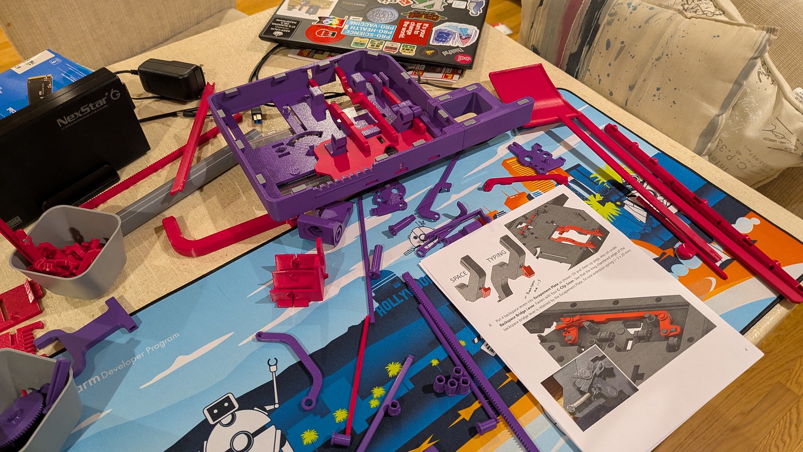
Most of the prints went well, but there were a few mishaps. MJ had to add a large brim along with the plate glue to the Paper Feed Panel.3mf because it shifted slightly during an overnight print, and things were not good in the morning. The printer figured out it had a problem much later while printing the platen core on the same plate, and thankfully MJ was able to salvage that and finish that print.


As I went through the instructions, there were a few sections which were somewhat unclear (Keenan might have fixed these by now, he’s been amazing with swiftly answering my questions!):
- The “Roller Rods” referenced Stage 2, Step 8 are “Lower Roller Axle” and “Upper Roller Axle”
- The following parts are logically lumped together as “Backspace Levers” in Stage 1, Step 8: Backspace End Lever.3mf, Backspace First Lever.3mf, Backspace Pawl.3mf
- The “Carriage Bridge” mentioned in Stage 1, Step 10 the the Carriage Main Bridge.3mf
- The following parts are all part of the “rest as shown” in Stage 1, Step 20: Margin Indicator Color Insert.3mf, Margin Indicator Lever.3mf, Margin Indicator Spring Lever.3mf, Margin Indicator Window.3mf, Margin Slider.3mf
- The Pivot Lever Axle.3mf is part of Stage 3, Step 9
In retrospect, some of this is rather obvious, but with over 150 little parts and some of them quite similar, it’s easy to get turned around, and you really don’t want to try to insert something where it doesn’t fit!
The screws on the base plate were definitely a challenge, I guess there’s a reason we don’t tend to make screws out of plastic. In spite of doing the test screw fit early in the process, I think I might have stripped some of them as they went in anyway. But they all made it in and everything snapped together, so I guess it’s not a problem! I do have to be careful when this matters though.
Speaking of not fitting, we had to reprint the Ratchet Spring Lever.3mf and Ratchet Locking Pawl.3mf because when I put them inside the holes of the Alignment Comb Right.3mf the fit was so tight that they wouldn’t move, and since springs were placed in the inset, it was obvious that they should move. Bringing the size of the shaft down to 97% seems to have done the trick (thanks MJ!).
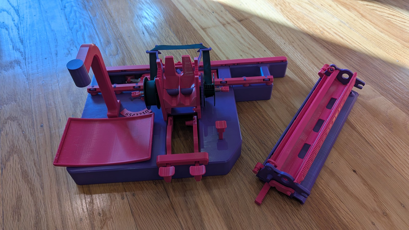
I then got the ribbon mounted and Stage 1 was complete! I have a couple springs that won’t quite stay put, and I’m concerned about the functionality of the Rachet Pawl, since it’s a really tricky fit and isn’t reliably catching on the Spool Advance Gear. I’m forging ahead though and will re-visit this when the rest is more complete.
We have several more pieces ready to print, but we decided to take a break from this and I’ve only just begun Stage 2 with the Carriage Assembly. It’s coming together though! Unfortunately we have a clog somewhere in our AMS that’s going to take some time to debug, and we’re leaving for a spring break trip back east next Friday, so here I pause our project!
We’ll complete you soon, dear Index Typewriter.